CemSim software function
CemSim was developed by Maurer Engineering Inc. The program runs in the Windows environment.
CemSim analyzes the complex phenomena of multistage fluid placement in a wellbore and is a very useful planning tool prior to field operations. Although generally designed for cementing (i.e., the text-box labels etc.), the program can be used for any multistage, multifluid pumping operation. The well-recognized U-tubing phenomenon is addressed, along with equivalent circulating density (ECD) and pressure at the bottom of the hole. The program predicts return rates during the job, including periods of free fall when the return rate is not well correlated with pump rate. A variety of potential problems with formation breakdown and of low to no returns can be avoided by using CemSim at the planning stage.
CemSim runs in the Microsoft Windows environment. It is assumed that the user is familiar with basic operation in Windows.
The important features of the CemSim Wellbore Cementing Model include:
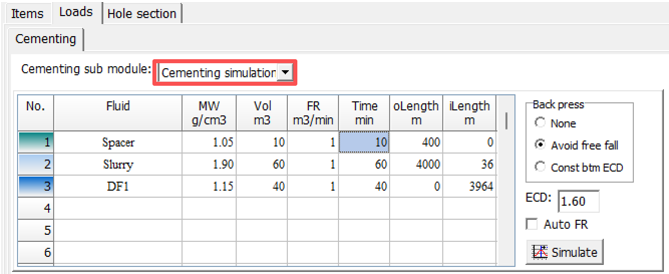
1. Manages up to 20 different fluid stages, and each can be pumped at 10 different rates, including shut-in periods
2. Allows up to 20 sections of casing and 20 well intervals
3. Handles vertical, deviated and horizontal wells
4. Calculates the length of the section where the fluid is in free fall
5. Computes pump pressure, and pressures and ECDs at up to three locations along the wellbore
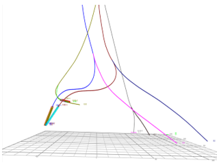
6. An animation feature is included that simulates multistage pumping operations and shows the position of fluid fronts as the job progresses
7. Provides a choice of systems of units, including English, SI (metric), or any user-specified custom combination
The Output Window provides a number of informative graphs and text reports including:
1. Simulation Report. All parameters calculated by CemSim in a convenient table format.
2. Flow Rate In and Out versus Elapsed Time. A comparison of inflow to returns shows the expected impact of free fall.
3. Free Fall and Fluid Fronts versus Elapsed Time. The length of the section in free fall and the position of the leading edge of each fluid stage are charted.
4. Pressure versus Elapsed Time. The pressure throughout the job is charted at a strategic location, typically at the bottom of the hole.
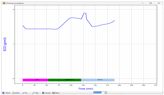
5. Equivalent Circulating Density (ECD) versus Elapsed Time. Pressure history at the zone of interest is also plotted as an ECD.
6. Free Fall Pit Gain versus Elapsed Time. The predicted effect of free fall on pit volume allows accurate operations planning.
7. Formation/Pipe Safety Check Report. This table report shows the minimum and maximum pressures expected during the job at multiple positions along the wellbore. These data highlight potential problems with lost circulation, fluid influxes, and casing collapse/burst.
8. Minimum/Maximum Annular Pressure Profile. Minimum and maximum pressures during the operation at the formation face are plotted for multiple positions along the wellbore.
9. Tubing Burst/Collapse Pressures. Minimum and maximum pressures for collapsing or bursting the casing are plotted for multiple positions along the wellbore.
Variables printed in the text report and curves plotted in the graphs can be selected by the user. All output data may be printed, copied to the Clipboard for export into other Windows applications, or stored to disk.